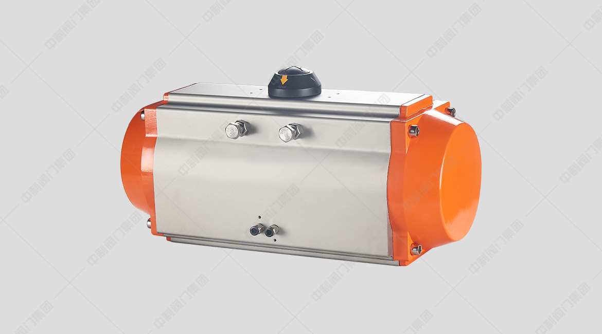
PRODUCT OVERVIEW
At series pneumatic actuator is a double piston rack and pinion rotating structure design, which is divided into double action and single action (spring return). Through the innovative and optimized design of CAD three-dimensional model, the shape is beautiful, compact and modern; The utility model material and new technology are adopted to make the quality and performance of the product more reliable; Multi specification selection is more economical; The products fully comply with international standards and technical specifications to meet current and future needs.
PRODUCT FEATURES
1. The extruded aluminum alloy cylinder block has a hard surface texture and strong wear resistance after hard oxidation treatment.
2. Compact double piston gear and rack structure, accurate meshing, stable transmission, symmetrical installation position and constant output torque.
3. F4 guide rings are installed at the moving parts of piston, rack and output shaft to achieve low friction, long service life and avoid metal contact.
4. The cylinder block, end cover, output shaft, spring and fasteners are subject to anti-corrosion treatment.
5. The spring of single pneumatic actuator is installed after preloading, which can be safely and conveniently disassembled and assembled.
6. The two-way stroke adjustment of 0 ° and 90 ° plus or minus 5 ° can be carried out in the fully open and fully closed positions.
7. The installation and connection dimensions comply with ISO5211, din3337, VD1 / vde3845 and numar standards to ensure interchangeability between and facilitate the installation of solenoid valves, limit switches and other accessories.
8. The mounting and connecting holes of the output shaft have a variety of shapes (square hole, shaft key hole and flat hole).
9. It has beautiful and exquisite appearance, light weight and waterproof sealing structure.
10. There are normal temperature type, high temperature type and low temperature type. Nitrile rubber shall be used under normal temperature working conditions, and fluororubber or silicone rubber shall be used at high or low temperature.
WORKING PRINCIPLE (ATD)
")
CCW:
Inlet A. compressed air overcomes the spring force. Push the piston outward, turn the actuator output shaft counterclockwise (0 ° → 90 °), and exhaust at port B;
The actuator loses air, the piston moves inward under the action of spring force, the output shaft of the actuator rotates clockwise (90 ° → 0 °), and the air is exhausted at Port A.
CW:
Inlet a, compressed air overcomes the spring force, pushes the piston outward, the actuator output shaft rotates clockwise (0 ° → 90 °), and outlet B exhausts;
The actuator loses air. The piston moves inward under the action of spring force. The output shaft of the actuator rotates counterclockwise (90 ° → 0 °) and vents at Port A.
OPERATING PRINCIPLE (ATE)
")
CCW:
Intake air from port a, the compressed air pushes the piston outward to rotate the actuator output shaft counterclockwise (0 ° → 90 °), and exhaust air from port B.
Intake air from port B, the compressed air pushes the piston inward to rotate the actuator output shaft clockwise (90 ° → 0 °), and exhaust air from Port A.
CW:
Intake air from port a, the compressed air pushes the piston outward to rotate the actuator output shaft clockwise (0 ° → 90 °), and exhaust air from port B.
Inlet port B, compressed air pushes the piston inward to rotate the actuator output shaft counterclockwise (90 ° → 0 °), and exhaust port a.
")
MAIN TECHNICAL PARAMETERS
|
spare parts |
Anti corrosion grade |
|
A |
B |
|
Cylinder block |
Anodic hardening |
The manual operating mechanism can manually open and close the valve |
|
End cap |
Metal polyester coating |
teflon coating |
|
output shaft |
Electroless nickel plating on carbon steel |
Carbon steel electroless nickel plating or stainless steel |
|
Use occasion |
General occasion |
General occasions or low concentration acidic environment |
MATERIAL OF MAIN PARTS
|
Part number |
Quantity per set |
Part name |
Standard material |
Selection of materials |
|
01 |
1(1) |
Left end cap |
Die cast aluminum alloy |
stainless steel |
|
02 |
1(1) |
Left end cap |
Die cast aluminum alloy |
stainless steel |
|
03 |
1 |
Cylinder block |
Extruded aluminum alloy |
stainless steel |
|
04 |
2 |
piston |
Die cast aluminum alloy |
- |
|
05 |
1 |
output shaft |
carbon steel |
stainless steel |
|
06 |
1 |
Adjusting cam |
stainless steel |
- |
|
07 |
2 |
O-ring (end cap) |
Nitrile rubber |
Fluorine or silicone rubber |
|
08 |
2 |
O-ring (piston) |
Nitrile rubber |
Fluorine or silicone rubber |
|
09 |
1 |
O-ring (bottom of output shaft) |
Nitrile rubber |
Fluorine or silicone rubber |
|
10 |
1 |
O-ring (top of output shaft) |
Nitrile rubber |
Fluorine or silicone rubber |
|
11 |
2 |
O-ring (adjusting bolt) |
Nitrile rubber |
Fluorine or silicone rubber |
|
12 |
2 |
Plug head (cylinder block) |
Nitrile rubber |
Fluorine or silicone rubber |
|
13 |
2 |
Bearing (piston) |
Fluorocarbon Composites |
- |
|
14 |
1 |
Bearing (top of output shaft) |
Nylon 46 |
- |
|
15 |
1 |
Bearing (top of output shaft) |
Nylon 46 |
- |
|
16 |
1 |
Guide bearing (back of piston) |
Nylon 46 |
- |
|
17 |
2 |
Thrust bearing (output shaft) |
Nylon 46 |
- |
|
18 |
2 |
Gasket (output shaft) |
Nylon 46 |
- |
|
19 |
1 |
Elastic retaining ring |
stainless steel |
- |
|
20 |
8/12/16(2) |
End cap bolt |
stainless steel |
- |
|
21 |
8/12/16(2) |
End cap gasket |
stainless steel |
- |
|
22 |
2 |
shim |
stainless steel |
- |
|
23 |
2 |
Nut |
stainless steel |
- |
|
24 |
2 |
Adjusting bolt |
stainless steel |
- |
|
25 |
2 |
Guide block |
Nylon 66+30%FG |
- |
|
26 |
5-12 |
Spring assembly |
Alloy spring steel |
- |
|
27 |
1 |
Position indicator |
polypropylene+30%FG |
-
|
|
28 |
1 |
screw |
stainless steel |
- |
")
MAIN OVERALL DIMENSIONS
| Outline and connection dimensions(mm) |
|
Type |
AT50 |
AT63 |
AT75 |
AT88 |
AT100 |
AT115 |
AT125 |
AT145 |
AT160 |
AT180 |
AT200 |
AT240 |
AT265 |
AT330 |
|
D/E |
|
ISO Flange |
F04 |
F05 |
F05-07 |
F05-07 |
F07-10 |
F07-10 |
F07-10 |
F10-12 |
F10-12 |
F12 |
F14 |
F16 |
F16 |
F16 |
|
A |
140.5 |
158.5 |
210.5 |
247.5 |
268.5 |
315 |
345 |
408.5 |
437.5 |
487 |
546 |
633 |
728 |
876 |
|
B |
26.5 |
30 |
30.5 |
32.5 |
37.5 |
42.5 |
45 |
47.5 |
52 |
58.5 |
62.5 |
78.5 |
165 |
187 |
|
C |
20 |
20 |
20 |
20 |
20 |
30 |
30 |
30 |
30 |
50 |
50 |
50 |
50 |
50 |
|
φD |
40 |
40 |
40 |
40 |
40 |
56 |
56 |
65 |
65 |
80 |
80 |
115 |
115 |
115 |
|
E |
59 |
72 |
84.5 |
97.5 |
111 |
127 |
136 |
156.5 |
169 |
190.5 |
213 |
251 |
298.5 |
383 |
|
F |
69 |
85 |
102 |
115 |
127 |
145 |
157 |
177 |
196 |
220.5 |
245 |
298.5 |
330 |
405 |
|
G |
29 |
36 |
42.5 |
49.5 |
56 |
64 |
69.5 |
80 |
88 |
99 |
110 |
131 |
163.5 |
201 |
|
H |
41.5 |
47 |
52 |
56.8 |
67 |
77 |
82 |
91.5 |
99 |
105 |
112 |
131 |
166 |
204.5 |
|
I |
14.5 |
14.5 |
14.5 |
14.5 |
14.5 |
24.5 |
24.5 |
24.5 |
24.5 |
44.5 |
44.5 |
44.5 |
44.5 |
44.5 |
| J min |
12 |
16 |
16 |
19 |
19 |
24 |
24 |
29 |
29 |
29 |
38 |
38 |
48 |
57 |
|
k |
11 |
11 |
17 |
17 |
17 |
27 |
27 |
27 |
27 |
36 |
36 |
36 |
36 |
36 |
|
L |
80 |
80 |
80 |
80 |
80 |
80 |
80 |
80 |
80 |
130 |
130 |
130 |
130 |
130 |
|
M |
30 |
30 |
30 |
30 |
30 |
30 |
30 |
30 |
30 |
30 |
30 |
30 |
30 |
30 |
|
N |
4 |
8 |
8 |
8 |
8 |
8 |
8 |
8 |
8 |
8 |
8 |
8 |
8 |
8 |
|
EO1 |
42 |
50 |
50 |
50 |
70 |
70 |
70 |
102 |
102 |
125 |
140 |
165 |
165 |
165 |
|
EO |
- |
- |
70 |
70 |
102 |
102 |
102 |
125 |
125 |
- |
- |
- |
- |
- |
|
P1 |
4-M6 |
4-M6 |
4-M6 |
4-M6 |
4-M8 |
4-M8 |
4-M8 |
4-M10 |
4-M10 |
4-M12 |
4-M16 |
4-M20 |
4-M20 |
4-M20 |
|
P |
- |
- |
4-M8 |
4-M8 |
4-M10 |
4-M10 |
4-M10 |
4-M12 |
4-M12 |
- |
- |
- |
- |
- |
|
口Q |
11 |
14 |
14 |
17 |
17 |
22 |
22 |
27 |
27 |
27 |
36 |
36 |
46 |
55 |
|
V |
24 |
24 |
24 |
24 |
24 |
24 |
24 |
24 |
24 |
24 |
24 |
40 |
40 |
40 |
|
W |
32 |
32 |
32 |
32 |
32 |
32.9 |
32 |
32 |
32 |
32 |
32 |
45 |
45 |
45 |
|
Y |
M5x8 |
M5x8 |
M5x8 |
M5x8 |
M5x8 |
M5x8 |
M5x8 |
M5x8 |
M5x8 |
M5x8 |
M5x8 |
M6x10 |
M6x10 |
M6x10 |
|
Z |
1/8" |
1/8" |
1/8" |
1/8" |
1/4" |
1/4" |
1/4" |
1/4" |
1/4" |
1/4" |
1/4" |
3/8" |
1/2" |
1/2" |
AIR CONSUMPTION OF ACTUATOR
Type | Open volume | Closed volume | Type | Open volume | Closed volume |
| AT032DA/SR | 0.03 | 0.04 | AT140DA/SR | 2.50 | 2.20 |
| AT040DA/SR | 0.05 | 0.06 | AT160DA/SR | 3.70 | 3.20 |
| AT052DA/SR | 0.12 | 0.16 | AT190DA/SR | 5.90 | 5.40 |
| AT063DA/SR | 0.21 | 0.23 | AT210DA/SR | 7.50 | 7.50 |
| AT075DA/SR | 0.30 | 0.34 | AT440DA/SR | 11.0 | 9.0 |
| AT083DA/SR | 0.43 | 0.47 | AT270DA/SR | 17.0 | 14.0 |
| AT092DA/SR | 0.64 | 0.73 | AT300DA/SR | 23.8 | 29.7 |
| AT105DA/SR | 0.95 | 0.88 | AT350DA/SR | 35.1 | 46.3 |
| AT125DA/SR | 1.60 | 1.40 | AT400DA/SR | 52.6 | 56.0 |