PRODUCT OVERVIEW
In order to improve the economy of the power plant, the steam turbine is equipped with regenerative system, that is, high and low pressure heater. In order to ensure that the heater operates with water level and prevent the steam extraction from the upper stage of the steam turbine from channeling into the next stage when the heater operates without water level, so as to reduce the efficiency of the steam turbine and the safety of the equipment, the drain control valve is set in the drain system of the heater, According to the water level signal of the heater, it automatically switches the drain valve and adjusts the opening of the valve to keep the water level of the heater within a certain range. The working conditions of drain control valve are very poor, and it works under two-phase fluid in many cases (i.e. steam water mixing state). Moreover, it operates under the throttling state, and the cavitation is quite serious. When the cavitation reaches a certain degree, it can not play the role of drain regulating valve. In this case, the heater can not guarantee the operation with water level, which reduces the economy of steam turbine operation. It can be seen that it is particularly important to select a drain regulating valve with small cavitation, low noise, simple structure and reliable performance.
WORKING PRINCIPLE
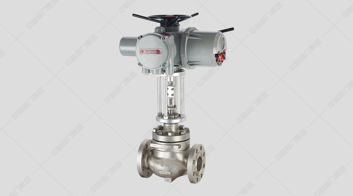
The electric drain regulating valve is composed of an electric actuator and a drain regulating valve. The input of the electric control valve is the DC electrical signal sent by the regulator, which is amplified by the servo amplifier and then drives the actuator to generate axial thrust and drive the action of the control valve, so as to cause the change of medium flow and adjust various parameters in the system. At the same time, the actuator sends a valve position signal for comparison with the servo amplifier to keep the regulating valve at the position corresponding to an input signal to complete the servo regulation task.
MAIN TECHNICAL PARAMETERS
| Nominal diameterDN(mm) |
50 |
80 |
100 |
150 |
200 |
250 |
300 |
| Flow characteristics |
Approximate linearity, approximate equal percentage |
|
Nominal pressurePN(MPa) |
2.5/6.4 |
| Connection type | welding |
| Equipped with actuator |
ZKD Type |
| Stroke L (mm) |
57.6 |
88.2 |
| Maximum differential pressure △ P (MPA) |
0.5/3 |
| Rated flow coefficient Cv |
44 |
99 |
175 |
395 |
640 |
1000 |
1440 |
| Operating temperature T (℃) |
≤450 |
≤450 |
|
Use media |
water |
Note: 1. This model also has flange type, right angle type and flange right angle type. 2. It can also be equipped with pneumatic actuator or HQ intelligent actuator.
MAIN TECHNICAL PERFORMANCE INDEXES
| project | Technical performance index |
| Basic error (%) |
No more than±2.5 |
| Return difference (%) |
≤1.5 |
| Dead band (%) |
≤3 |
| Leakage |
0.01%×Valve rated capacity |
MATERIAL OF MAIN PARTS
| Name | Material Science |
| Valve body |
WCB、WC6、20CrMo |
| Spool | 316 Stainless steel |
| Shrouded |
17-4PH |
| Valve stem |
17-4PH |
| Valve seat | 316 Stainless steel |
MAIN OVERALL CONNECTION DIMENSIONS
| Nominal diameterDN(mm) |
50 |
80 |
100 |
150 |
200 |
250 |
300 |
|
H |
860 |
918 |
918 |
918 |
1460 |
1690 |
1690 |
|
H1 |
120 |
248 |
248 |
248 |
360 |
470 |
470 |
|
L |
300 |
372 |
372 |
372 |
490 |
610 |
610 |
|
D1 | 90 |
150 |
180 |
200 |
244 |
355 |
420 |
|
D2 | 76 |
104 |
127 |
168 |
210 |
270 |
320 |
|
D3 | 50 |
80 |
100 |
140 |
180 |
230 |
270 |